Ten feet more width comes with a taller profile and a different framing arrangement. See where the steel changes, then choose the space your operation needs.
2.0 → 2.5 mmMain tube wall
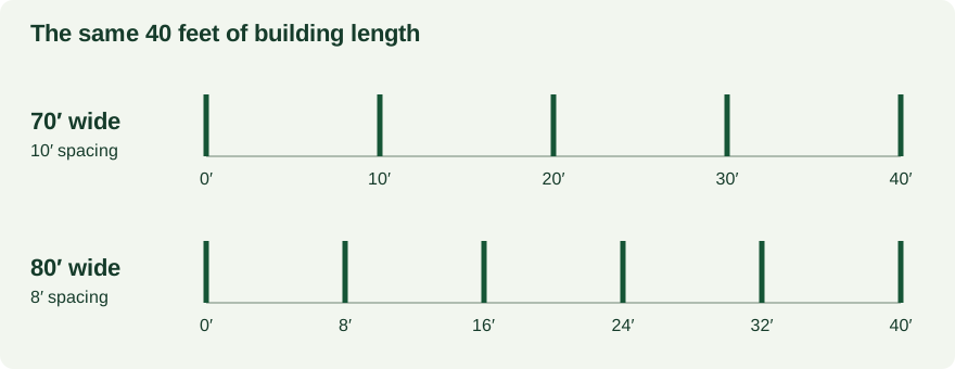
10 → 8 ftApprox. frame spacing
Connection bracesAdditional tubular supports on 80′
Inside the cover
Two frames, side by side.
Both buildings use trussed steel arches and steel purlins. The 80-wide adds thicker main tube walls, closer frame spacing and the tubular bracing shown below.
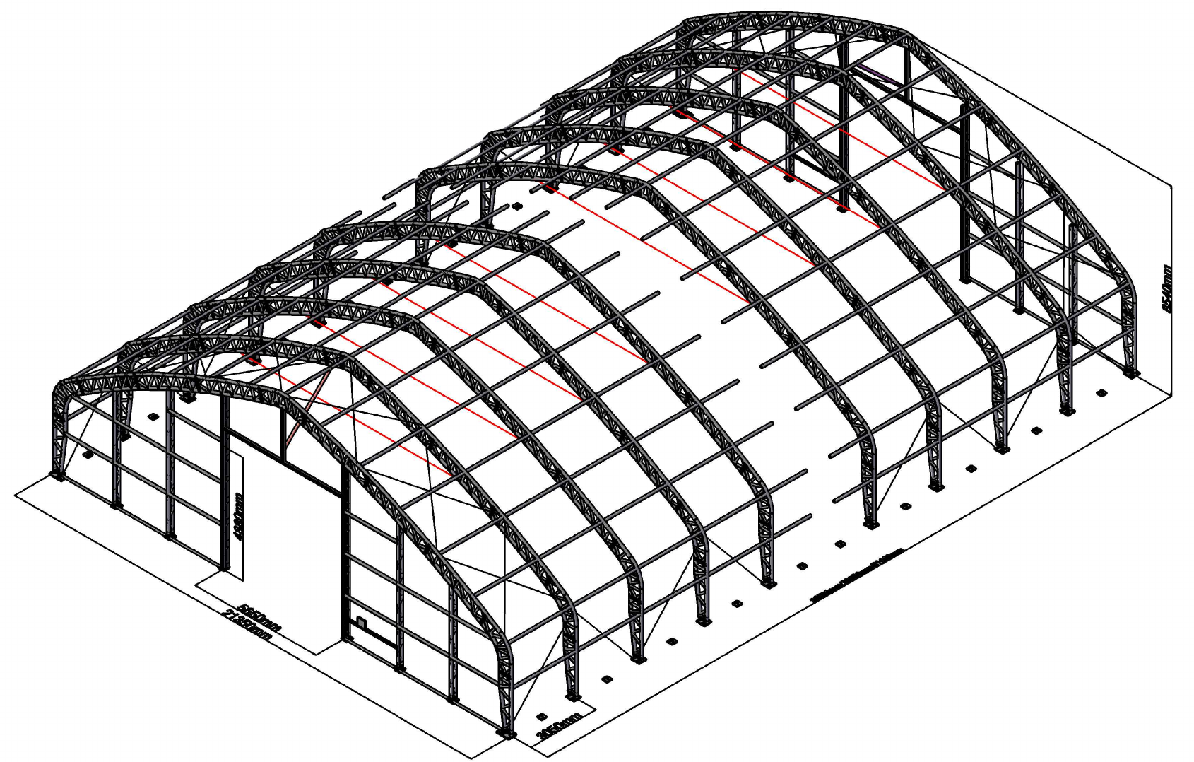
70′ standard
Trussed arches, steel purlins and steel-wire bracing. This family drawing has a break in its length.
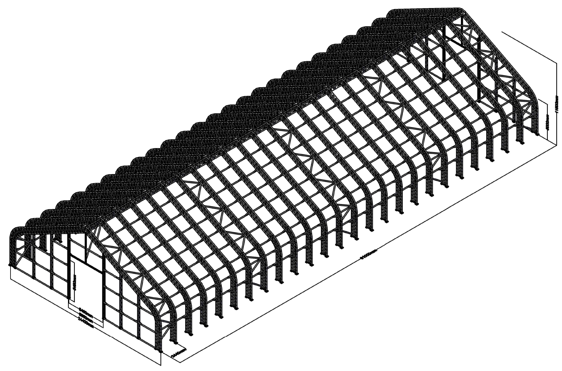
80′ Industrial
The 200-foot arrangement shows more closely spaced frames and additional tubular bracing.
Excerpts from the supplied drawing sets, independently enlarged. The 70 view has a length break; the 80 view shows the full 200-foot arrangement. These perspective views are not at a common scale. Tap either drawing to inspect it.
Look at the intersections
The support detail explains the difference.
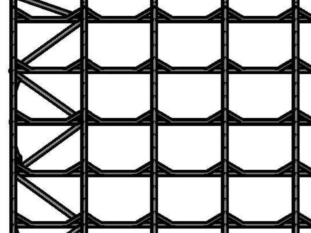
Purlins run along the building between its arches. In the 80-wide roof drawing, short tubular braces repeat where these members meet the frames. Larger tubular diagonals brace selected bays. These are separate from the web members inside each trussed arch.
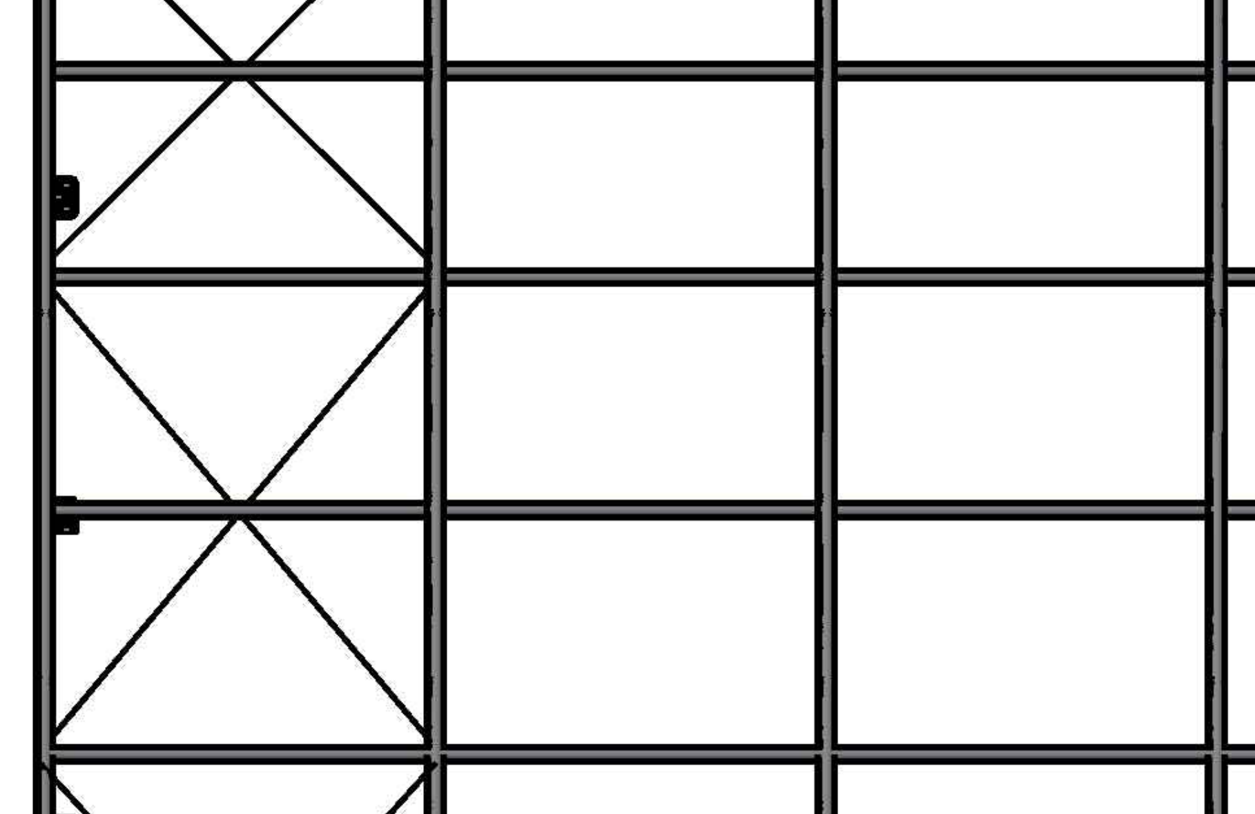
70′ roof framing
Steel purlins + wire bracingThe diagonal wires cross the designated braced bay. Both models use steel purlins.
80′ roof framing
Short braces + bay diagonalsLook for the small triangular supports at the purlin/frame intersections, separate from the long diagonal braces.
Roof-plan excerpts enlarged for inspection, not to a common scale. The 70 manual identifies its steel-wire arrangement; the 80 drawing shows the tubular arrangement. The complete supplied layout determines the actual brace locations. Cable bracing is a structural system, not a sign that the 70 is incomplete.
More frame positions along the same length.
Frame spacing changes from approximately 10 feet to 8 feet. At 200 feet long, the compared layouts have 21 and 26 frame positions, including both ends: five more frames on the 80.
Spacing illustration only. The drawing dimensions are 3,050 mm and 2,440 mm. This is not an assembly layout or a load-capacity comparison.
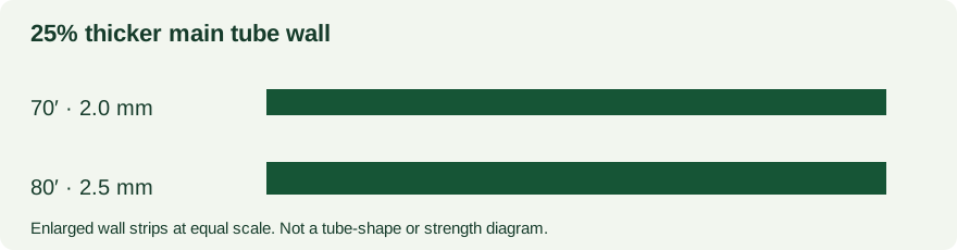
Thicker wall. Measured in millimetres.
Both compared main-tube designations start at 76 mm. The wall changes from 2.0 to 2.5 mm: a 25% increase in nominal wall thickness. The purlin specification remains 60 × 1.5 mm in the reviewed documents.
Wall thickness is not steel grade, total steel weight or a percentage increase in building strength. We use the actual metric wall thickness rather than an ambiguous gauge number.
The specifications that change your decision.
Compare
70′ standard
80′ Industrial
Main arch tube designation
76 × 2.0 mm
76 × 2.5 mm
Nominal wall thickness
2.0 mm
2.5 mm
Frame spacing
3,050 mm · approx. 10 ft
2,440 mm · approx. 8 ft
Purlin tube specification
60 × 1.5 mm
60 × 1.5 mm
Bracing shown
Steel-wire bracing in the documented arrangement
Repeated short roof connection braces; tubular diagonals in selected bays
Frames at 200 ft
21 frame positions
26 frame positions
PVC cover
750 g/m²
900 g/m²
Nominal width / peak
70 ft / 28 ft
80 ft / 37 ft
Door reference, width × height
5.49 × 4.88 m
5.49 × 5.49 m
Standard 70′ / 28′-peak configuration versus 80′ / 37′-peak Industrial. The 70′ / 32′-peak option is separate. Nominal dimensions and drawing opening references do not guarantee usable interior clearances. Both have the same published 12-year prorated fabric and 2-year manufacturing warranty, subject to written terms.
Published prices
Compare the same length and purchase scope.
70 × 200 × 28 ft and 80 × 200 × 37 ft · CAD + tax
Same length. Same scope.
70′ standard
80′ Industrial
Nominal footprint
14,000 sq ft
16,000 sq ft
Building kit
$83,888
$160,888
Kit / nominal sq ft
$5.99
$10.06
Installation base
$43,000
$69,000
Installed from
$126,888
$229,888
$77,000 more for the 80′ kit, with 2,000 more nominal square feet and the taller Industrial configuration.
Installed from = building kit + published installation base, assuming an install-ready site. Site preparation, site-specific engineering, tax, and equipment, travel or lodging supplied by MAX are additional where applicable. Confirm each item in your quote.
MAX arranges delivery. Delivery is included within 888 highway km of the hub supplying your order. Unloading is the customer’s responsibility unless your written quote states otherwise. Check delivery scope.
If equipment, access aisles, storage and usable clearances work within the 70-wide configuration, its lower purchase price can make it the better choice. If floor area is the constraint, compare adding length where your site allows it.
The extra width and taller profile may solve an access or operating-space requirement. Measure the equipment and how you use it. The nominal 37-foot peak does not mean that height is available at the doorway or across the floor.
The reviewed door references are approximately 18 × 16 feet for 70-wide and 18 × 18 feet for 80-wide. The entrance gets taller, not wider. Confirm the actual clear opening for your order.
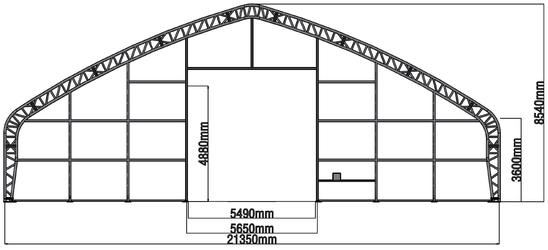
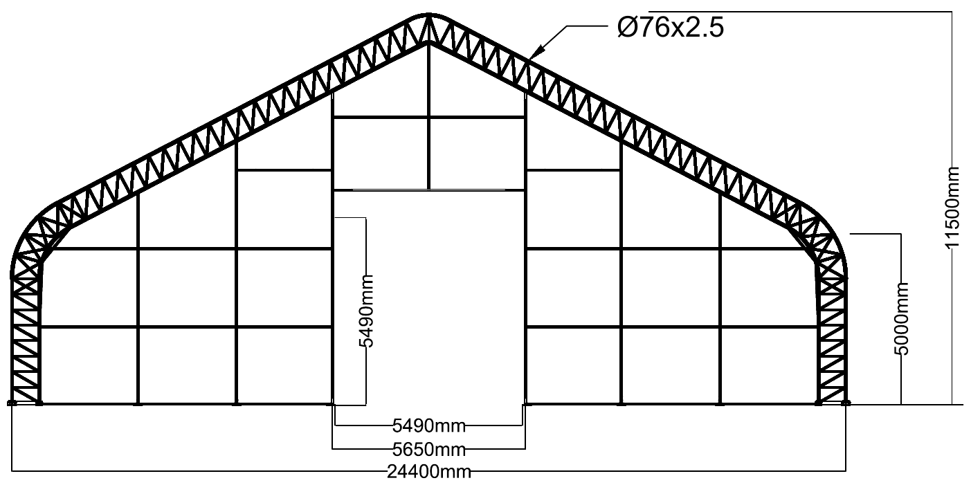
Inspect the profile and doorway drawings
70′ profile
Drawing references: 21,350 mm width, 8,540 mm height; door 5,490 × 4,880 mm.
80′ profile
Drawing references: 24,400 mm width, 11,500 mm height; door 5,490 × 5,490 mm.
Independently enlarged source views. Drawing height references differ from rounded sales dimensions; confirm current supplied drawings and usable clearances. These views are not equipment-fit guarantees.
Why the price doesn’t rise by just 14%.
Moving from 70 to 80 feet adds about 14.3% nominal floor area at the same length. It also changes the building’s height, frame spacing, wall thickness, bracing arrangement and cover specification. The quoted product is a different configuration.
A wider and taller structure changes the engineering problem. Its complete design includes the arches, purlins, braces, connections, foundations and site loads. Those component differences help explain the product; they do not calculate its retail price or prove a comparative load rating.
Does 25% thicker mean 25% stronger?
No. It describes nominal main-tube wall thickness only. Building capacity depends on the complete design and applicable site requirements.
Is the 70-wide missing supports?
No. It uses its documented steel-wire bracing arrangement. The 80 uses the different tubular arrangement shown here. Compare the complete configuration for your project.
Does the 80 have a brace at every purlin?
The reviewed drawings show repeated short braces at roof purlin connections. Use the actual supplied connection schedule to confirm each location; these excerpts do not establish a universal count.
Are installation and stamped engineering included in the kit price?
Installation is a separate service. Supplied manufacturer drawings are not provincially stamped site-specific engineering. Confirm your installation scope, foundation, local requirements and any additional engineering in your project quote.
Can I compare a 70-wide with a 32-foot peak?
Yes. That is a separate configuration and is outside the standard 70/80 structural comparison here. See the 70 × 200 × 32 and request its specific clearances and documents.
Compare both for your site.
Tell us your location, what needs to fit, equipment dimensions and intended timing. We’ll help compare the appropriate building and complete project scope.
Source review: 2026-09-24. Drawing excerpts: standard 70-wide family arrangement and 80 × 200 Industrial arrangement; steel-wire identification checked against the 70 × 200 assembly manual. The diagrams explain components, not erection methods. Confirm the current supplied configuration before ordering. Engineering notes.